 Open Access



 Open access
 Check for updates

Abstract
This paper investigates the design and performance analysis of a helical gear-pinion system intended for a reducer gearbox, which operates at a pinion speed of 1800 rpm and a power supply of 5 hp under moderate shock conditions for 8 to 10 hours daily. Using carbon steel (SAE 3150) for both parts, the study runs mathematical modelling to assess critical parameters and then designs it through SolidWorks integrated with GearTrax. Finite Element Analysis (FEA) conducted in ANSYS assesses the mechanical behavior under load, revealing a maximum deformation of 1.4672×10⁻² mm, maximum directional deformation (X-axis) of 1.2994×10⁻² mm, maximum equivalent (von Mises) stress of 125.79 MPa, and maximum principal stress of 138.99 MPa, all within acceptable limits for the material. The findings indicate that the gear-pinion system can operate reliably without premature failure. This research contributes to understanding gear design and performance, providing a foundation for future studies on material optimization and real-world operational conditions.
Introduction
Gear mechanisms are essential for effective power transmission and precise motion control applications for mechanical engineering. Gears are the most critical part of many machines, from machinery in industrial applications to automotive transmissions, because they allow mechanical forces, or torque, to be transmitted between two possibly misaligned axes. Designing a gear system is a challenging configuration of multiple parameters, including load, speed, material properties, and operating conditions [1],[2]. For shock-loaded applications, the correct design and development of gears to accommodate these stresses and strains within their working environment is vital [3],[4].
Helical gears are designed and modelled based on the module, pressure angle, Helix angle, etc. [3]-[6]. Contact stresses, bending stresses, and tooth deformation can be assessed through finite element analysis (FEA) to optimize gear speed and life [2]-[9]. Singh et al. [8] analyzed spur, bevel, and helical gears with ANSYS, emphasizing total deformation and equivalent stress, and found that helical gears exhibited the least deformation and stress. A comparative study of bending and contact stresses in helical gears using analytical as well as Finite Element Analysis (FEA) was reported by Venkatesh & Murthy [9] in their paper. This study concluded that the number of teeth significantly affected the induced bending stress. Gidado et al. [10] presented the design, modelling, and analysis of helical gears based on bending strength using AGMA and ANSYS.
The current paper aims to evaluate the performance and durability of a helical gear-pinion system under specified operating conditions. The total deformation, equivalent (von Mises) stress, max principal stress, and directional deformation were analyzed using the body's Finite Element Analysis (FEA) results. Those indicators offered significant insights into the performance of the gear-pinion system and aided in identifying potential failure vulnerabilities.
Modeling of Gear
Mathematical Computation
A helical gear-pinion mechanism is used in a reducer gearbox to reduce 1800 rpm of pinion speed. The operation is with moderate shock for 8 to 10 hr./day. The power supplied is 5 hp. Specification of gear and pinion:
Diametral pitch, Pd = 8.8; Pressure angle, Φn=20°; Helix angle, Ψ=30°; Number of teeth in gear, Ng =49; Face width, b =1.5 in.; Number of teeth in pinion, NP =24.
We aim to ascertain whether the gear and pinion mechanism will operate smoothly without premature failure if both are made from carbon steel (SAE 3150). This practical problem is analyzed using the equations and catalog provided in chapter 14 of the book Design of Machine Elements by V.M. Faires [10].
Let, gear ratio = mg, Pitch diameter = Dp,
Now, Pitch Diameter, Dp = Np/Pd = 2.4/8.8 = 2.727 in.
According to Equation (a), Page-357 [10],
Gear ratio, mg = Ng/NP = 49/24 =2.041
According to Appendix Table 26 [10], BHN=300+300=600 and Kg=233
Q = 2mg/(mg+1) = 2×2.041/(2.041+1) =1.3423
According to Buckingham’s limiting wear load equation,
Wear load, Fw = bDpQKg/cos²ψ [10]
⇒Fw = (1.5×2.727×1.3423×233)/cos²(30°)
=1705.77 lb. = 7589 N
Designing using SolidWorks
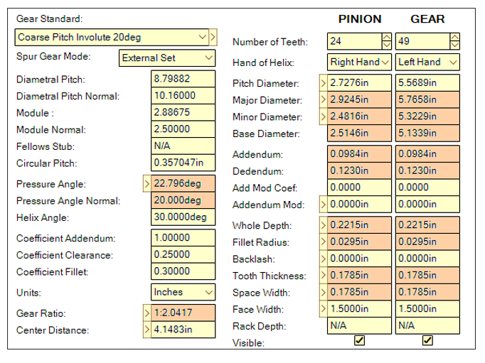
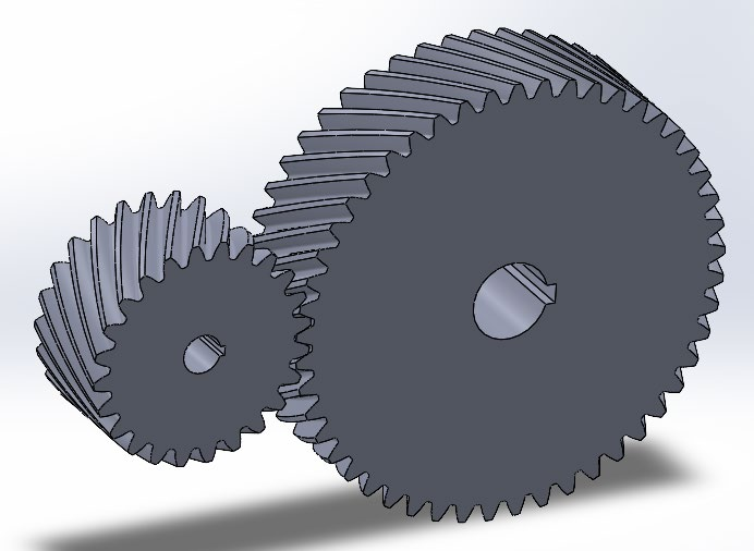
The gear was modelled using GearTrax and integrated with SolidWorks 2021. The dimensions used are shown in Figure 1. GearTrax streamlined the process by automating gear geometry and ensuring compliance with industry standards. Figure 2 illustrates the assembly of the gear and pinion.
FEM Package
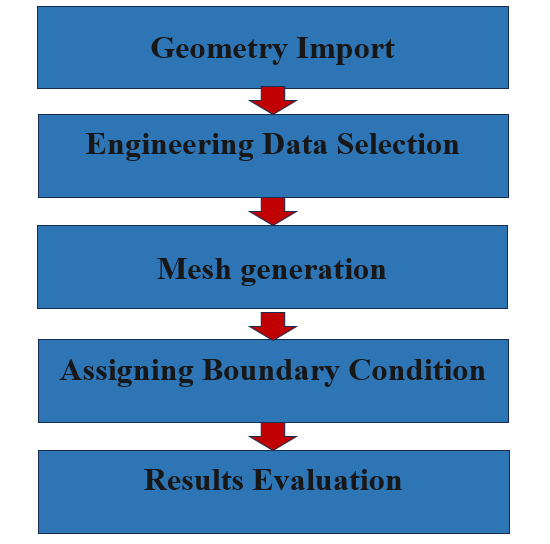
The Finite Element Analysis (FEA) was carried out using ANSYS, one of the several FEM packages. ANSYS is a general-purpose computer-aided engineering software application for mechanical finite element analysis (FEA) that combines solver, post-processing, and pre-processing modules into a single graphical user interface [11]. The steps followed in the analysis process using ANSYS is shown in Figure 3.
Boundary Condition
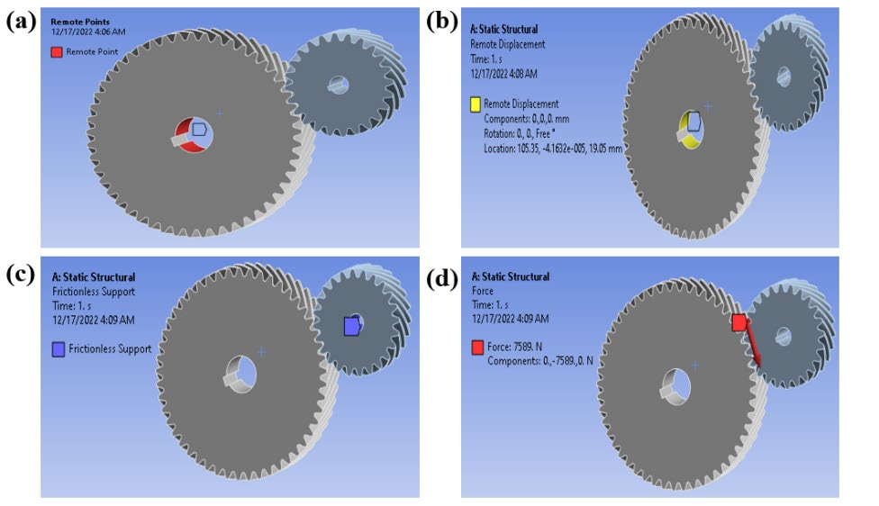
The boundary condition is illustrated in Figure 5. The remote point was positioned at the central location of the gear, and the remote displacement was limited to rotation alone around the z-axis. The inner face of the pinion was equipped with frictionless support. The wear load calculated before (7589 Newtons) was applied around the contact point of the gears. The stress concentration in the area was neglected.
Engineering Data Selection
An illustration of the properties of SAE 3150, which was used as material for both gear and pinion, is provided in Table 1.
| Ultimate tensile strength | 1041.1 MPa |
| Yield tensile strength | 896.32 MPa |
| Compressive Yield Strength | 250 MPa |
| Shear Modulus | 7.69×10¹⁰ Pa |
| Density | 7850 kg/m3 |
| Young Modulus | 2×10¹¹ Pa |
| Poisson’s Ratio | 0.3 |
| Thermal Conductivity | 60 W/mK |
Mesh Generation
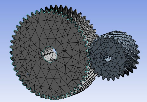
Mesh was produced after choosing engineering data, as illustrated in Figure 4. In this study, the determination of the element order was delegated to the program, allowing it to determine whether to generate models using linear elements (without mid-side nodes) or quadratic elements (with mid-side nodes). Solid elements are beneficial for solving problems involving three-dimensional stress analysis [11].
Result and discussion
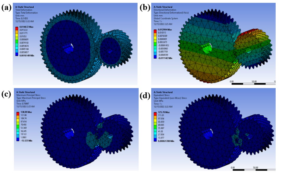
Figure 6 shows the result of total deformation, directional deformation (X-axis), maximum principle stress, and equivalent (von Mises) stress. The maximum, minimum, and average values of corresponding parameters are shown in Table 2. The average deformation was 9.4562×10⁻³ mm, which provides an indication of the level of deformation under the given loading conditions. The maximum principal stress values ranged from -15.125 MPa to 138.99 MPa, with an average of 1.096 MPa. The minimum value of the equivalent (von Mises) was 0.0061708 MPa, the maximum stress was 125.79 MPa and the average stress was 2.2341 MPa. The Finite Element Analysis (FEA) results demonstrated that the helical gear-pinion system could function efficiently within the specified parameters. Given the operational parameters, the greatest observed deformation was 1.4672×10⁻² mm, which is considered low. Furthermore, the calculation of equivalent (von Mises) stress showed a peak stress of 125.79 MPa, much lower than the yield strength of SAE 3150. This shows that the material is capable of withstanding the applied loads without yielding or deforming permanently. This result is important because it shows that, in normal conditions, the gear-pinion system should operate without any problems or premature failure.
| Total deformation | Directional deformation (X-axis) | |||||
|---|---|---|---|---|---|---|
| Minimum [mm] | Maximum [mm] | Average [mm] | Minimum [mm] | Maximum [mm] | Average [mm] | |
| 1.6149×10⁻³ | 1.4672×10⁻² | 9.4562×10⁻³ | -1.1142×10⁻² | 1.2994×10⁻² | 8.4174×10⁻⁵ | |
| Maximum principle stress | Equivalent (von Mises) stress | |||||
| Minimum [MPa] | Maximum [MPa] | Average [MPa] | Minimum [MPa] | Maximum [MPa] | Average [MPa] | |
| -15.125 | 138.99 | 1.096 | 6.1708×10⁻³ | 125.79 | 2.2341 | |
Ethical Approval
This work has never been published before in any format or language.
Conclusions
This study exemplifies ways to analyze and design the helical gear-pinion system using modern simulation tools. The results of this study established a sound basis for further research and practical applications concerning designing gear systems under tough operating conditions. Although the results are positive, it is important to consider several limitations. The virtually idealized circumstances in which the Finite Element Analysis (FEA) was performed may not be precisely commensurate with the complexities of real-world operations. It also does not consider the impact of lubrication, wear-in effects between the gears or the effect of manufacturing tolerances on operational performance.
Consent of Participate
No human subject or living organism/tissue is involved in this research.
Consent to Publish
No consent to publish is to be shared.
Declarations
- Author contributions
The concept for this work was developed with input from all authors especially Md. Nahid Hossan and Mst.Sharifa Khatun. Hriday Kumar Gharamy, Anik Molla, and Ehasanul Islam Rafi modeled the design. The simulation was carried out by Md. Jahirul Islam and Hriday Kumar Gharamy. The manuscript was written by Hriday Kumar Gharamy and Anik Molla. All writers read and approved the final manuscript.
- Funding
The authors affirm that they did not receive any funding for this manuscript.
- Data availability
Not applicable
- Competing interests
Not applicable
- Acknowledgments
Thanks to the Department of Mechanical Engineering, Rajshahi University of Engineering & Technology.
References
- 1.Tamilselvam, P., (2023). Theoretical and analytical research on load sharing in helical gear with evaluating the FEA method and computerized approach of AGMA standards. Journal of Combinatorial Optimization, 45(3): 87.
- 2.Kumar, G. S., and Krishnappa, G. B., (2022). Design and finite element analysis of AISI 4340 alloy steel helical gear. Materials Today: Proceedings, 65: 3671-3674.
- 3.Netpu, S., and Srichandr, P., (2013). Failure of a helical gear in a power plant. Engineering failure analysis, 32: 81-90.
- 4.Feng, W., Feng, Z., and Mao, L., (2020). Failure analysis of a secondary driving helical gear in transmission of electric vehicle. Engineering Failure Analysis, 117: 104934.
- 5.Mote, M. S. A., Gaur, A. V., and Gujale, M. A. B., (2018). Design and FEM analysis of helical gear. International Journal of Engineering Research and Advanced Technology (IJERAT), 14.
- 6.Adin, H., and Adin, M. Ş., (2021). Numerical analysis of damaged helical gear wheel. Batman Üniversitesi Yaşam Bilimleri Dergisi, 11(1): 43-56.
- 7.Afolalu, S. A., Kayode, J. F., Adaramola, B., Monye, S. I., Ikumapayi, O. M., Oloyede, L., & Tunbosun, O. A. (2024, April). The Design and Simulation of Helical Gear. (2024). International Conference on Science, Engineering and Business for Driving Sustainable Development Goals (SEB4SDG) (pp. 1-12). IEEE.
- 8.Singh, A. K., Kumar, S., Agrawal, B. N., & Nain, P. K. S. (2022). Design and Analysis of Spur Gear, Helical Gear, and Bevel Gear by Using ANSYS. In Advances in Manufacturing Technology and Management: Proceedings of 6th International Conference on Advanced Production and Industrial Engineering (ICAPIE)—2021 (pp. 641-650). Singapore: Springer Nature Singapore.
- 9.Venkatesh, J., and Murthy, M. P., (2014). Design and structural analysis of high speed helical gear using Ansys. International journal of engineering research and applications, 2(3): 215-232.
- 10.V.M. Faires, (1971). Design of Machine Elements. The Macmillan Company.
- 11.X. Chen and Y. Liu, (2014). Finite element modeling and simulation with ANSYS workbench, 10.1201/b17284.
Cite this article
Journal
Gharamy HK, Molla A, Rafi EI, Islam MJ, Hossan MN, Khatun MS. Design and Finite Element Analysis of Helical Gear-Pinion Mechanisms: Assessing Mechanical Behavior. JoSEP. 2026;2(1):105-108. doi: 10.62275/josep.25.1000016.
Rights and permissions
© 2026
Cited by (0)
Citing works are not available yet.
About this article
- Received
- 30 September 2024
- Revised
- 6 November 2024
- Accepted
- 12 November 2024
- Published
- 22 October 2026
- Journal
- Journal of Science and Engineering Papers
- Volume / Issue
- 2 / 1
- Pages
- 105-108
- DOI
- 10.62275/josep.25.1000016